keyman64
programmable keyboard interceptor and hardware control system

The keyman64 is a programmable keyboard interceptor and hardware control system for computers equipped with a simple 64-key matrix keyboard.
It is installed between the keyboard and the computer, continually scanning the keyboard matrix and relaying the keyboard state to the computer using a crosspoint switch. To the computer, the crosspoint switch matrix looks just like a physical keyboard, while the keyman64 gains the ability to intercept keystrokes and control the matrix seen by the computer.
The keyman64 can be configured to intercept special key combinations and invoke arbitrary sequences of commands to alter the state of sixteen general purpose control lines provided on the board. These lines can be used to control additional hardware instead of using physical buttons or switches.
Thus the keyman64 eliminates the need to install physical switches or buttons into the computer case.
Additional features include the ability to send predefined keyboard macros or to redefine the keyboard layout. Commands can also be sent from a remote PC via USB, or send on simple serial wire interface, allowing remote control from either a PC or another microcontroller or similar device.
For some concrete examples of what the keyman64 can do, see the configuration examples.
Documentation is available in both english and german.
Overview
Basic mode of operation
During normal operation, the device simply relays all keyboard events to the computer, except when a special key defined as the meta key is held down. As long as this key is held down, any additional key presses invoke the user-defined command sequences bound to the respective key. When the meta key is released again, the device continues to relay keyboard events to the computer.
If no special key has been pressed while the meta key was down, a press of the meta key itself is simulated on the matrix seen by the computer. This way the meta key is not lost, it can still be pressed as usual in order to type the associated character. The only difference is that the computer will notice the simulated key down and up events only after the physical key has been released.
This scheme works well if the meta key only needs to be pressed once, but not if the meta key is supposed to be held down for a longer period of time. But this can still be accomplished by using a key combination invoking the down command for the meta key itself, for example:
m: down ARROWLEFT
Assuming that the arrow-left key is used as the meta key, this binding
can be invoked by holding down arrow-left and pressing m. The
virtual arrow-left key now appears held down to the computer as long
as the physical meta key is kept down. Once the physical meta key is
released, the device beings scanning and relaying the physical
keyboard state again, effectively releasing the virtual meta key seen
by the computer.
The meta key defaults to the arrow-left key. To change it to a different key, use the meta command described below.
Software
A simple commandline configuration and control utility is provided. Its main purpose is to convert a plain text configuration file into a binary format. The binary configuration file is flashed to the Atmegas EEPROM Memory. See Configuration for details.
In addition, the utility allows remote control of the keyman64 via USB. Arbitrary commands can be send via USB and will be immediately executed on the keyman64.
Hardware design
The device is based on an Atmega1284p, a crosspoint switch IC and some discrete 74xx logic ICs. Supported crosspoint switches are the CD74HC22106 or the MT8808 in either DIP or PLCC package. A USB socket is provided to allow easy configuration and firmware updates using a USB bootloader preinstalled on the Atmega. Please see design documents in the source distribution and the relevant sections in this document for further details.
Compatibility
In theory, the device should work with any computer using a passive 8x8 matrix keyboard. However, the layout of the connectors and the keynames follow those of the C64. Also the type command will use key combinations specific to the C64 to type the ASCII characters given as the argument. If you need software support for a different homecomputer, please feel free to post a feature request on the github issue tracker, preferably providing the required information.
Documentation
- Downloads
- Errata
- Ordering Assembly Kits
- Building the hardware
- Installing the firmware
- Configuring USB devices on the PC
- Installing the configuration and control utility
- Configuration
- Configuration and control utility
- Port expansion
- Serial interface
- Configuration examples
- Licensing
Downloads
Source
The source distribution includes the sources for the firmware and the configuration utility as well as schematics and pcb layouts in KiCad format for building the hardware.
Latest stable is keyman64-1.6.tar.gz.
All releases can be found under /download/keyman64
Latest developments are available via github:
git clone https://github.com/hbekel/keyman64
The Changelog lists all changes in detail.
Binaries
-
keyman64-1.6.msi
configuration utility, Windows 32-bit installer package -
keyman64-bootloader-updater-1.6.hex
updates the bootloader, suitable when updating from versions prior to 1.4 using the already installed bootloader -
keyman64-application-and-bootloader-1.6.hex
keyman64-application-and-bootloader-1.6.bin
combined images containing both bootloader and application, suitable for use with an external programmer -
keyman64-application-1.6.hex
keyman64-application-1.6.bin
contains only the application part of the firmware -
keyman64-gerber-r4.zip
Gerber files for pcb revision 4
Schematics

Errata
Revision 3
The USB level conversion circuit is not correct in this and all previous revisions. This may result in missing USB functionality. It obviously depends on the specific type of 3.6V zener diodes used. While the diodes I have shipped with revisions 1 and 2 seem to have worked (more by accident than by design), the ones shipped with revision 3 boards have failed to work properly, so I have only discovered this error after shipping revision 3.
In order to fix an already assembled board or when assembling the board, the diodes have to be soldered in like this:

As you can see, the cathodes have to go directly to the D- and D+ lines from the USB socket. You can solder them directly to the leads of the 68Ω resistors, given that you installed them as suggested by the silkscreen.
This error has been fixed with revision 4
Revision 2
The negative voltage generator ICL7660 is not required, although it does not hurt to leave it in. It has been removed in favor of an alternative PLCC socket in Revision 3.
Also, the mounting holes added in this revision are 3mm in diameter, which makes them unsuitable for mounting using common self-adhesive pcb holders, which require at least 4mm holes. The holes have been changed to 4mm in Revision 3.
Ordering Assembly Kits
I’m offering assembly kits including the keyman64 pcb, the preprogrammed Atmega and all required components (except connection cables) for 30€ each. Worldwide shipping via regular mail is free of charge.
You can order kits via email at henning.liebenau@protonmail.com
To place an order, please include the word “keyman64” in the subject. State your full name, your complete international shipping address and the number of kits you wish to buy. Note that orders are limited to a maximum of two kits per person. You will receive an email containing payment information (bank transfer only). You will have to pay in advance to confirm your order.
Notes on availability
I try to keep a sufficent number of kits on stock, but please note that I’m doing all of this in my spare time, on a short budget and a minimal profit margin. My primary motivation is to serve the community, not to run a profitable business.
This means that in case I am currently out of stock, it may take a few weeks until I can put together a new batch of kits to fullfill your order. I may even need to collect a sufficient number of prepaid orders before I can afford to order the necessary parts myself. In these cases I will regularily inform you about the status of your order. Thus some patience and trust may be required on your part.
Building the hardware
Please refer to the list of parts and the placement on board below below.
Power supply
+5V must be supplied to the center pin of J1. You can either supply +5V from the computers main board directly to this pin, or use a jumper bridge to supply power from pin 4 of P1 (the mainboard keyboard socket) or from the USB socket. To supply power from the mainboard socket, bridge the left and center pin of J1. To supply power from USB, bridge the center and right pin of J1.
Supplying power from the USB socket is only recommended for standalone operation of the keyman64, i.e. when P1 it is not connected to the io ports of a computer and none of the external devices connected to the keyman64 are powered from a different source. In general, all devices involved (the computer, the keyman64 and the devices controlled by it) must be powered from the same source. For example, if the keyman64 was configured to source power over USB and the computer is powered on without the USB cable being connected, the keyman64 might still sink current over the ESD-protection diodes of the Atmels io ports from the io ports of the computer or the external devices, which might cause severe damage to any of the io ports involved.
Connections
The pin layouts of P1 and P2 follow the layout of the C64 keyboard connector. The RESTORE line is simply passed through on the board.
List of parts
| Reference | Type | Value | Package/RM |
|---|---|---|---|
| C1 | Ceramic capacitor | 18pF | 2.5mm |
| C2 | Ceramic capacitor | 18pF | 2.5mm |
| C6 | Ceramic/film capacitor | 100nF | 2.5mm |
| C7 | Ceramic/film capacitor | 100nF | 2.5mm |
| C8 | Ceramic/film capacitor | 100nF | 2.5mm |
| C9 | Ceramic/film capacitor | 100nF | 2.5mm |
| C10 | Ceramic/film capacitor | 100nF | 2.5mm |
| C11 | Ceramic/film capacitor | 100nF | 2.5mm |
| D1 | Zener Diode | 3.6V | DO-204 |
| D2 | Zener Diode | 3.6V | DO-204 |
| R1 | Precision Resistor | 1k5 | 6.5mm, ∅ 2.5mm |
| R2 | Precision Resistor | 68 | 6.5mm, ∅ 2.5mm |
| R3 | Precision Resistor | 68 | 6.5mm, ∅ 2.5mm |
| P3 | USB Mini-B Socket | - | Through-Hole |
| SW1 | Push Button | - | 6x6mm print |
| SW2 | Push Button | - | 6x6mm print |
| X1 | Quartz Crystal | 16Mhz | HC49/U-S |
| U1 | 74HC22106 or MT8808 | - | DIP28 |
| U2 | Atmega1284P | - | DIP40 |
| U3 | 74HC00 | - | DIP14 |
| U4 | 74HC4051 | - | DIP16 |
| U5 | 74HC4520 | - | DIP16 |
| U6 | 74HC4051 | - | DIP16 |
| U7 | 74HC22106 or MT8808 | - | PLCC28 |
For the crosspoint switch you can either use an MT8808 or a 74HC22106, and you can either use U1 for a DIP28 package or U7 for a PLCC28 package version.
When using a 74HC22106, you will have to configure the device accordingly by executing the configuration command using at startup.
IC-Sockets are not listed.
Placement on board

Installing the firmware
If you bought an assembly kit from me, the Atmega is already programmed with the latest firmware and bootloader versions and is ready to use.
Otherwise, if you have no means of initially programming the Atmega yourself then you can send it to me and I will prepare it for you. Just drop me a line at henning.liebenau@protonmail.com.
Installing the combined firmware image
The easiest way to bootstrap the Atmega is to install the combined binary image. The image contains both the bootloader and the application part of the firmware. If you have a programming device capable of programming the complete PROGMEM area from a single binary image or intel hex file (e.g. the TL866), use this method.
Note that you also have to check and eventually program the fuses of the Atmega as well. The required fuse values are:
    Low:      0xd7
    High:     0xd0
    Extended: 0xfc
This corresponds to the following fuses programmed: SUT1, CKSEL3, SPIEN, EESAVE, BOOTSZ0, BOOTSZ1, BOOTRST, BODLEVEL0, BODLEVEL1. All other fuses must remain unprogrammed.
Installing the bootloader manually
The Atmega1284p must contain the USBaspLoader, which must be uploaded to the Atmega via ISP prior to installing it on the board.
There is a preconfigured version of the bootloader in the source tarball.
Change to the bootloader directory and edit the Makefile.inc and
adjust the PROGRAMMER settings to according to your setup. Then
issue
$ make flash fuse
The Atmega can now be installed on the device. When entering the bootloader, it identifies itself to the host like this:
16c0:05dc Van Ooijen Technische Informatica shared ID for use with libusb
It can be accessed using avrdude -p m1284p -c usbasp <commands...>
Note that you may need to configure the USB devices on your system beforehand.
Entering the bootloader
To manually enter the bootloader, hold down the BOOT Button and press the RESET button, then release the BOOT button again.
Once the device is installed you can configure a key combination using the boot command. For example, by using
b: boot
you can enter the bootloader simply by pressing <meta>-b.
You can also just send the boot command via USB from the PC:
$ keyman64 boot
Updating the bootloader
Eventually firmware updates will require an update of the bootloader already installed on the device.
For this purpose, an updating application is provided in keyman64-bootloader-updater-1.6.hex.
To upgrade, connect and power on the keyman64 and enter the existing bootloader, then run
$ avrdude -p m1284p -c usbasp -U flash:w:keyman64-bootloader-updater-1.6.hex
This will overwrite the existing application code (i.e. the keyman64 application), run the updater application and thus update the bootloader.
After this, manually enter the bootloader and proceed by reinstalling the keyman64 application as described in the following section.
Installing and updating the firmware
Once the Atmega is equipped with a USB bootloader the application part of the firmware can be installed with the following command:
$ avrdude -p m1284p -c usbasp -U flash:w:keyman64-firmware-1.6.hex
If you have build the firmware from source you can use the program
target of the toplevel Makefile as well.
Since version 1.4 the firmware can also be updated using the update
command:
$ keyman64 update keyman64-firmware-<version>.bin
This will automatically enter the bootloader and update the firmware.
Since version 1.5 the update command also accepts firmware images in
Intel HEX format. The file extensions .bin and .hex are recognized
and determine the respective file format.
Since version 1.6 the update command accepts a configuration file as
an optional second argument. If a configuration file is specified, the
update command will first disable the existing configuration on the
device, then update the firmware and finally recreate and flash the
configuration from the specified file to the device. This is required
for updates which change the binary configuration format. If this
procedure is necessary, it will be explicitly stated in the release
notes and Changelog.
Configuring USB devices on the PC
The keyman64 implements two separate USB devices, a remote control device and a bootloader device.
During normal operation, the remote control device will be active and accessible from the PC using the configuration and control utility. This device will identify itself to the host using the following properties:
| Vendor | OpenMoko, Inc. |
| Manufacturer | Henning Bekel |
| Device | Keyman64 |
| Vendor ID | 1d50 |
| Product ID | 60e9 |
While in bootloader mode, the bootloader device will be accessible from the PC. This device will identify itself to the host using the following properties:
| Vendor | Van Ooijen Technische Informatica shared ID for use with libusb |
| Manufacturer | www.fischl.de |
| Device | USBasp |
| Vendor ID | 16c0 |
| Product ID | 05dc |
Linux
On Linux, the required udev rules are installed alongside the configuration and control utility. After installation, issue
# udevadm control --reload-rules
When in bootloader mode, the bootloader device will be symlinked to
/dev/usbasp. During normal operation, the keyman64 control device
will be symlinked to /dev/keyman64. These symlinks are created with
file permissions 0666, allowing access for any user.
Windows
Once you connect one of the usb devices for the first time, Windows will insist on trying to download and install a driver for these devices. Since both devices are general purpose USB devices, this is futile, since there simply are no drivers for windows to install. You must abort the windows driver installation dialog to prevent windows from permanently marking the device as unusable due to its perceived lack of “proper” drivers.
Instead, use the Zadig tool to generate and install minimal drivers that simply associate the devices with the subsystems required for general purpose access.
Run Zadig, connect the usb cable to the keyman64 and power up the
device. Zadig should now detect the Keyman64 device. Install the
WinUSB driver for this device.
Now enter the bootloader. The Zadig tool
should now detect the USBasp device. For use with the keyman64
client, install the WinUSB driver for the bootloader device. For use
with avrdude, install the libusb-win32 driver for this device. In
this case, also make sure that the libusb0.dll is present on your
system (it should come with avrdude). If not, follow the link for
libusb-win32 shown in the “More information” section of the Zadig
window and install libusb-win32 on your system.
Installing the configuration and control utility
Binary
For the windows version, use the binary installer
package. This will also install the required
libusb-1.0.dll. The installation directory will be added to your
PATH environment variable.
Source
Linux & MacOSX
libusb-1.0 and corresponding development packages (if any) need to
be installed on your system.
Extract the tarball, change to the source directory and type make.
Use make install to install the keyman64 binary into
/usr/local/bin. The PREFIX variable can be used to install with a
different prefix, e.g. use make PREFIX=/usr install to install into
/usr/bin instead. The DESTDIR variable can be used for a staged
install.
On linux, the udev rules required for the USB devices will be
installed to /etc/udev/rules.d as well. As root, run
# udevadm control --reload-rules
after installation.
Windows
If you’re using cygwin you can build a windows binary in the same way
as under Linux or MacOSX. The required packages are libusb-1.0 and
libusb-1.0-devel. Note that the resulting binary will still need
cygwin dlls to be present.
A native win32 binary can be build using mingw32 under Linux or
Cygwin. If necessary, edit the Makefile and adjust the MINGW32
variable to the proper prefix for your toolchain. Then use make
win32 to build keyman64.exe.
Configuration
The configuration file is a plain text file containing configuration commands and keybindings in a human readable format. Using the keyman64 utility this file is converted to a binary format which can be flashed into the EEPROM memory of the Microcontroller. See Transferring the configuration.
Syntax
Whitespace and comments
Empty lines as well as leading and trailing whitespace characters are ignored. Whitespace is only significant to separate individual tokens and keywords.
Comments begin with a hash character # and continue for the
remainder of the current line.
Keywords
All keywords, like command and key names, as well as user defined
symbols are case-insensitive. E.g. CLEAR is equivalent to
clear, SPACE is equivalent to space and so on.
Commands and bindings
Each line must contain one command specification, optionally prefixed by a key specification:
[<key>:][<policy>] <command> [<arguments>]
If no key specification is given, the command will be executed on powerup/reset of the microcontroller, and can thus be used to configure the initial state of the device.
If a key specification is given, the command will be bound to the specified key.
If multiple commands are bound to the same key, the commands will be executed in sequence, in the order in which they appear in the configuration file.
Command sequences can also be bound to “slots” by using numeric key
specifications between $40 and $F9. These command sequences can
not be invoked directly by a key combination, but may be invoked
indirectly via the exec command.
The optional policy argument can be set to either 0 or 1, meaning
odd or even. If odd, the command will only be executed on the first,
third, fifth etc. time the key is pressed. If even, the command will
only be executed on the second, fourth, sixth etc. time the key is
pressed.
For example, this feature can be used to implement switching a port line from tristate to low or from low to tristate using only a single key binding:
tristate a0

S:0 clear a0
S:1 tristate a0
In this example, the port line a0 is initialized to tristate on
startup first. If you press <meta>-s for the first time, the port line
is pulled to ground, if you press it the next time, the line is set to
tristate again, and so forth.
Keynames
Keys can be specified by using literal key names like DEL, A,
RUNSTOP or ONE. To obtain a list of valid key names and their
synonyms, run keyman64 --keys.
Keys may also be specified by number, denoting the key position in the C64 keyboard matrix. Keys are numbered from left to right, from row 0, column 0 down to row 7, column 7.
Thus $00 corresponds to the DEL key, $3f denotes the RUNSTOP
key.
Key numbers may be given in decimal or hexadecimal
notation. Hexadecimal numbers must be prefixed with a dollar sign $
or the literal string 0x.
Ports
The sixteen control lines are organized into two 8-bit wide ports. For
commands modifying the state of these control lines, the respective
port can be specified using the keyword port, followed by the
literal string a or b:
port [a|b]
Bits
Commands modifying the state of the control lines can be limited to individual bits or ranges of successive bits. Bits are denoted by a decimal number in the range 0-7.
bit <n>
bits <s>-<e>
Where n denotes an individual and s and e denote the start and
end bit of a bitrange (inclusive).
Short notation for ports and bits
As of version 1.6 control lines and ranges of control lines can be specified with a short notation combining the existing notations for ports and bits:
<port>[[<s>][-<e>]]
Thus expressions like port a bit 3 or port b bits 0-2 can be shortened
to a3 or b0-2 respectively.
Durations
Durations can be specified by a series of decimal values and unit specifiers:
[<n><unit>...][<n>]
Available unit specifiers are d, h, m, s, ms for days,
hours, minutes, seconds and milliseconds respectively. If no unit
specifier is given, the preceding value is interpreted as
milliseconds.
The maximum possible duration is 232 milliseconds, about 49 days. Specifications that exceed this value will be truncated accordingly.
Examples:
1m30s = one minute and thirty seconds
1s500 = one second and fivehundred milliseconds
10 = ten milliseconds
Values
Values can be specified in hexadecimal or binary notation. Hexadecimal
values need to be prefixed with $. Binary values need to be prefixed
with %
Symbols
Custom symbols can improve the readability of the configuration file. They are defined using simple name/value pairs.
<name> = <value>
Symbol names must consist of alphanumeric characters, digits and underscores only. If a symbol name equals one of the reserved key or command names, a corresponding error message will be issued.
Once a symbol has been defined, any subsequent occurrence is replaced by its literal value. If a symbol is used before it is defined, an error message will be generated.
For example, this configuration
    r: clear port a bit 0
    r: sleep 10
    r: tristate port a bit 0
can be made easier to read and change:
    RESETLINE = port a bit 0
    RESET = r

    RESET: clear RESETLINE
    RESET: sleep 10
    RESET: tristate RESETLINE
Commands for configuration and maintenance
using
using <8808|22106>
Specify which crosspoint switch IC is installed in the device. Either
a CD74HC22106 or an MT8808 may be used. Default is 8808.
speed
speed <fast|slow>
Specify the speed at which the keyboard matrix is scanned. Fast mode is the default and should work well in most setups. Slow mode is required when the length of the cable is significantly longer than the stock keyboard cable, e.g. when installing the device in a Commodore SX64.
Note that selecting slow mode will not impact the responsiveness of the keyboard in any way. Both modes are still quite fast in scanning the keyboard.
expand
expand ports=<n> clock=<line> data=<line> latch=<line> enable=<line>
Configures a port expansion of <n> daisy chained 74595 serial shift registers, where the CLOCK, DATA, LATCH and ENABLE lines of the first shift register in the chain are connected to the respective native port lines.
Note that in this case the port lines need to be specified in short notation.
See port expansion for details.
meta
meta <key>
The meta command defines the meta key to be used. Default is ARROWLEFT.
boot
boot
Enter the bootloader and expect configuration or firmware updates via USB. The device will remain bootloader mode until a new configuration or firmware has been programmed or the reset button has been pressed.
When sending the boot command via the remote USB interface, e.g. by
executing keyman64 boot on the PC, the firmware will immediately
jump into the bootloader without properly terminating the current USB
communication properly, which will result in the following
non-critical error message:
error: could send usb control message: Pipe error
This message can be ignored as long as the AVR has successfully entered the bootloader.
save
save
Permanently saves the current state of the control lines to eeprom. This state can be restored later using the restore command.
restore
restore
Restore the state of the control lines that were stored in eeprom by a
preceding save command. If no state has been saved before, all
lines are set to tristate.
memorize
memorize
Temporarily memorize the current state of the control lines to RAM. This state can be restored later using the recall command.
recall
recall
Restore the state of the control lines that was stored in ram by a
preceding memorize command. If no state has been memorized before,
all lines are set to tristate.
Commands for modifying control lines
set
set <port> [<bits>] [to <value>]
Sets the specified bits of the specified port to the specified value. If value is omitted, it defaults to setting all bits to 1 (high). If bits are omitted, sets all bits of the specified port.
Examples:
set port a bit 3 to 1 – sets bit 3 of port a to high
set port b bits 3-4 to 2 – sets bit 3 to low and bit 4 to high on port b
set port a – sets bits 0-7 to high
clear
clear <port> [<bits>]
Clears the specified bits of the specified ports, i.e. sets them to 0 (low). If bits are omitted, clears all bits of the specified port.
tristate
tristate <port> [<bits>]
Tristates the specified bits on the specified port. If bits are omitted, tristates all bits on the specified port.
Tristating a line means setting it to a high-impedance state which is neither high nor low. This is equivalent to physically disconnecting the line.
invert
invert <port> [<bits>]
Inverts the state of the specified bits on the specified ports. If bits are omitted, inverts all bits of the specified port. If a bit has been set to tristate beforehand, it will be set to output high.
increment
increment <port> [<bits>]
Increment the state of the specified bits on the specified port by one. If bits are omitted, increments the state of all bits on the specified port.
This can be used to implement a binary counter on a port or a specific bit range on a port. If all bits are already set (e.g. the counter has reached its maximum) then all bits are cleared again.
Example of a four-bit binary up-counter in the lower part of port a:
increment port a bits 0-3
decrement
decrement <port> [<bits>]
Decrements the state of the specified bits. Works similar to the
increment command.
Commands for controlling the keyboard matrix
down
down <key>
Holds down the key on the matrix seen by the computer. The key will
remain held down until an up command for the key is executed or the
meta key is released.
up
up <key>
Releases the specified key on the matrix seen by the computer. The key
will remain released until a down command for the key is executed or
the meta key is released.
press
press <key>
Presses the specified key on the matrix seen by the computer, i.e. the key is held down for 20 milliseconds and then released again. This is a shortcut for
down <key>
sleep 20
up <key>
type
type <string>
Types the specified string on the matrix seen by the computer. To
insert a press of the RETURN key, add the escape sequence \r.
Lower case ASCII characters will cause the corresponding key to be pressed without modifiers. Upper case and special characters will be pressed in conjunction with the required modifier to type the correct character.
To type PETSCII characters that are not present in the ASCII character set, you can simply use the ASCII character at the respective position in the ASCII table. For example, the pound symbol, which is at position 92 in the PETSCII table, can be specified by using the corresponding ASCII backslash character.
Alternatively, any PETSCII character can be typed by inserting it using a numeric escape sequence, specified in either decimal or hexadecimal notation:
\xnn   -- hexadecimal notation, e.g. \x0a
\{ddd} -- decimal notation, e.g. \{147}
In addition, the following escape sequences are predefined:
\\ -- literal backslash, (0x5c) (pound-symbol on the C64)
\r -- return (0x0d), equivalent to pressing RETURN
\n -- newline (0xa), equivalent to pressing SHIFT-RETURN
\f -- form feed (0x0c), equivalent to pressing SHIFT-CLRHOME
Note that the keyman can only type those characters that can actually be typed on a real C64 keyboard. This excludes the PETSCII-codes for explicitly setting the character set (upper or mixed case, codes 14 and 142) and for locking/unlocking manual switching of character sets (codes 8 and 9).
Example (on the C64):
type load"*",8,1\r – types LOAD"*",8,1 and presses RETURN
swap
swap <key> <key>
Swaps the specified keys against each other before relaying them to the computer. This can be used to redefine the keyboard layout, e.g. to switch to a QWERTZ layout on the C64:
swap Z Y
Note that this applies only to the keys relayed to the computer, not
to the keys interpreted as a part of a key binding. Commands bound to
the physical key Z can still be invoked by pressing <meta>-Z in
this example.
map
map <port> <bit> to <key>
Maps the specified control pin to a key. The control pin becomes an active-low input pin and will hold down the specified key when low.
Note that once mapped, a pin should not be modified by other commands in any way.
password
password
Interactively set the password used for unlocking the keyboard after it has been locked using the lock command. The C64 needs to be in direct mode for this as the keyman prompts for the password by simply typing on the keyboard.
The password needs to be entered twice. If both passwords match, the password is permanently stored in EEPROM memory.
To clear the password, simply enter an empty password, i.e. hit return twice.
lock
lock
If a password has been set using the password command, the keyboard will be locked and no keys will be passed through to the computer until the user enters the correct password followed by RETURN.
Any commands bound to the virtual key LOCKED will be executed before locking the keyboard. Likewise, any commands bound to the virtual key UNLOCKED will be executed before unlocking the keyboard again.
Commands for controlling execution
exec
exec <key>|<slot>
Executes the command sequence bound to the specified key or slot number. Execution of the current command sequence will resume after the specified sequence has been executed.
sleep
sleep <duration>
Suspend execution of the current command sequence for the specified duration. No keyboard processing will occur during sleep, e.g. key presses will neither be relayed nor interpreted as bindings.
requires
<key>: requires <n>
This directive instructs the keyman to execute the command sequence
bound to the respective key only after n consecutive presses of
the key have been registered while the meta key is being held down.
This is useful to protect against accidental executions of a disruptive action, such as resetting the machine while having unsaved changes in an editor. For example, the following reset sequence requires three presses to execute:
r: requires 3
r: clear port a bit 0
r: sleep 20
r: tristate port a bit 0
This only applies to interactive use, i.e. exec r will still run the
above sequence immediately.
Commands for displaying information
version
version
Types out the current firmware version and build date. Note that the C64 has to be in direct mode for the text to appear on screen.
status
status
Types out the current state of the control lines. Note that the C64 has to be in direct mode for the text to appear on screen.
The state of the control lines will be displayed similar to this:
A XXXX0010
B 11111001
Where 0 is low, 1 is high and X is tristate.
Configuration and control utility
$ keyman64 --help
Keyman64 v1.6
Copyright (C) 2016 Henning Bekel.
License GPLv3: GNU GPL version 3 <http://gnu.org/licenses/gpl.html>.
This is free software: you are free to change and redistribute it.
There is NO WARRANTY, to the extent permitted by law.

Usage:
      keyman64 [<options>] convert [<infile>|-] [<outfile>|-]
      keyman64 [<options>] configure [<infile>]
      keyman64 [<options>] update <firmware> [<config>]
      keyman64 [<options>] reset
      keyman64 [<options>] <command>
      keyman64 [<options>] <script>|-

  Options:
           -v, --version  : print version information
           -h, --help     : print this help text
           -d, --device   : specify usb device (default: /dev/keyman64)
           -D, --delay    : delay in ms between commands
           -k, --keys     : list key names and synonyms
           -p, --preserve : deprecated as of version 1.5
           -i, --identify : request firmware identification via USB

  Files:
           <infile>   : input file, format is autodetected
           <outfile>  : output file, format determined by extension
           <script>   : script file containing keyman64 commands
           <firmware> : binary or ihex firmware image (.bin or .hex)

           *.conf : plain text config file format
           *.bin  : binary file format (default)

           Optional arguments default to stdin or stdout

  Command:
            (any valid keyman64 command)
Transferring the Configuration
Version 1.4 and later
As of version 1.4 the configuration file can be converted and flashed
to the keyman64 in one step using the configure command:
$ keyman64 configure keyman64.conf
This will parse the configuration file keyman64.conf, convert it to
a binary format and transfer it to the Atmega’s eeprom memory. When
finished, the keyman64 will be reset and the new configuration should
become effective.
The previous method described below can still be used alternatively.
Versions prior to 1.4
The convert command of the configuration and control utility is used
to convert the configuration file to a binary format which can then be
written to the Atmega1284p’s EEPROM memory over USB.
Assuming you have written a configuration file named keyman64.conf,
you can convert it using
$ keyman64 convert keyman64.conf keyman64.bin
If no errors are encountered this results in the file
keyman64.bin.
Make the keyman64 enter the bootloader.
Then use avrdude to write the configuration to the EEPROM memory:
$ avrdude -p m1284p -c usbasp -U eeprom:w:keyman64.bin:r
After the configuration has been transfered, the keyman64 will reset and the new configuration should be in effect.
Please note that the bootloader will reset the AVR immediately after the update operation has completed, even before the current USB communication between the bootloader and avrdude has been completed. This results in the following non-critical error message from avrdude:
error: usbasp_transmit: usb_control_msg: sending control message failed
This message can be ignored as long as avrdude reports that it has successfully written and verified eeprom contents.
Preserving saved state when updating the configuration
Note that the –preserve option is no longer necessary in versions 1.5 and later, since saved state is no longer overwritten when transferring a new configuration.
If the current eeprom contains a saved control state, this state will
be lost if a new binary configuration is created using the convert
command, since the eeprom will be flashed with new values.
In order to preserve a saved state, the --preserve option may be
used in conjunction with the convert command. The utility will then
try to obtain the currently saved state of the control lines via USB
and insert this state into the newly created binary
configuration. Thus the device has to powered up and connected via
USB.
Note that when using the configure command described above, any
saved state will be preserved automatically.
Remote control
Any command can be send from the PC via USB to the keyman64, where it will be executed immediately.
A single command can be executed by passing it directly on the commandline, e.g.
$ keyman64 press F5
If no arguments are specified on the commandline, the keyman64 utility will read commands from STDIN, where one command can be given on each line. Note that the commands will get parsed and executed after STDIN has been closed, e.g. all commands have been entered/piped in:
$ keyman64
reading commands from stdin...
> type load"$",8\r
> sleep 5s
> type list\r
> ^D
$
If the first argument to the keyman64 utility is a file, commands will be read from this file and subsequently sent to the keyman64.
Thus you can create a file containing a script like the following:
exec rightshift
press f5
press cursordown
press cursordown
press cursordown
press return
and run this script via
$ keyman64 --delay 250 script.txt
The --delay option will add an additional delay of 250ms after each
command. This avoids having to add explicit sleep commands in the
script.
On Linux and MacOSX, the she-bang mechanism can be used to create an executable script. Just make the script executable and add an appropriate she-bang line at the top, e.g.
#!/usr/bin/keyman64 --delay 250
press f5
press cursordown
press return
then chmod +x the script and you can execute it like any other
command.
Port expansion
As of version 1.6 the number of available control lines can be expanded by connecting one or more daisy chained 74595 serial shift registers. Four of the existing control lines need to be connected to the first (or only) 74595, while each 74595 added to the chain will add another 8-bit control port.
The 74595 is available on easily chainable breakout boards from various sources, for example the Artekit shop offers a breakout board well suited for this purpose.
The expand configuration directive is used to tell the keyman64 about the number of available additional ports and which of its native control lines are connected to the required pins of the first shift register. Once configured, the expanded ports will be labeled alphabetically beginning with the letter “c”. They can be used just like the existing ports a and b in other configuration directives and commands.
The expand directive names the required shift register pins as CLOCK, DATA, LATCH and ENABLE. Depending on the datasheet or breakout-board used, these pins may be named differently:
| Keyman64 | 74595 pin number | Description | Other common names on breakout-boards or in datasheets |
| CLOCK | 11 | shift register clock input | CLK, SCK, SHCP, SRCLK |
| DATA | 14 | serial data input | DS, SER, SER-IN |
| LATCH | 12 | storage register clock input | STCP, RCLK |
| ENABLE | 13 | output enable input (active low) | OE, EN |
| RESET | 10 | serial clear input (active low) | MR, CLR, SRCLR |
The ENABLE and RESET signals should be pulled up via a 4.7k resistor. (This is already the case for the artekit board linked above).
When the keyman starts up, all expanded ports will be initially tristated. Once any of the expanded port lines is set or modified by a command, all registers will be enabled, and all port lines whose state has not explicitly defined yet will be driven low by default.
Note that the virtual ports cannot be used as inputs and cannot be put into tristate, thus the commands map and tristate are not allowed to be used with expanded port lines. The configuration utility will issue an appropriate error message in this case.
Example
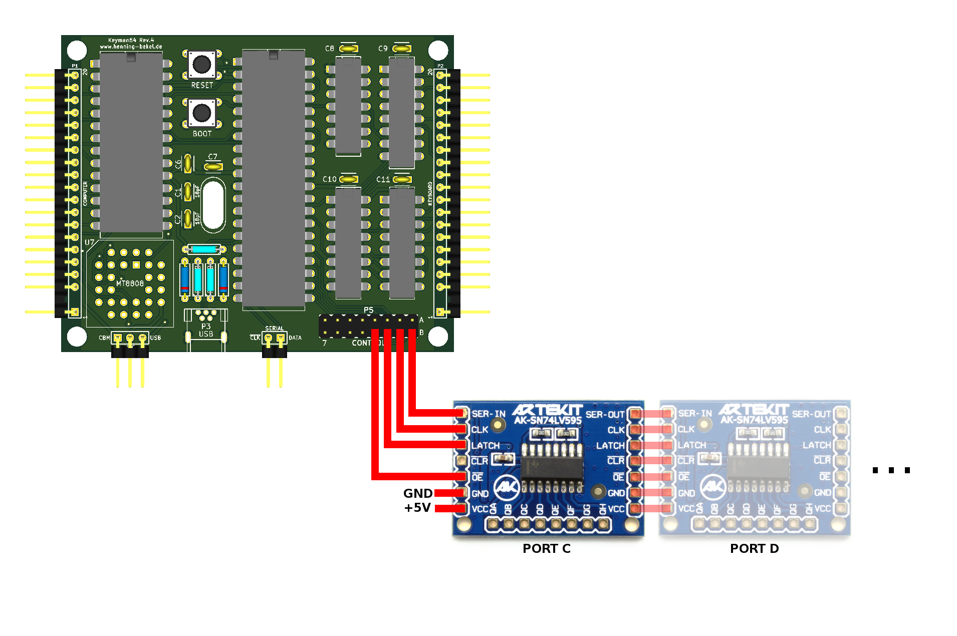
This illustration shows how to wire one or more 74595 breakout boards. Here the lower four control lines of port b are connected to the 74595.
The corresponding expand directive for using two additional ports is thus:
expand PORTS=2 DATA=b0 CLOCK=b1 LATCH=b2 ENABLE=b3
Any command following this directive in the configuration file can now refer to the additional ports as ports c and d, e.g.
X: set port d bit 5
Y: inc port c bits 0-1
Serial interface
The P4 connector offers a simple serial interface allowing remote control of the keyman64 by external hardware. The left pin provides the input for an active-low clock signal (denoted as /CLK on the board). The right pin provides the data input (denoted DATA). On the falling edge of the clock signal the value present on the data input is transferred to the keyman64.
Each command consists of a command-byte, followed by one or more
argument bytes. Bytes are transferred individually in little-endian
order, i.e. the least significant bit is send first. For example, to
press RUNSTOP, the actual command looks like this:
00000100 00111111 => 0x4 (command) 0x3f (argument)
but must be transferred like this:
00100000 11111100 => command, then argument, both lsb first.
The following commands are available:
00000001 <key>: execute command sequence bound to key or slot number00000010 <key>: hold the specified key down00000011 <key>: release the specified key00000100 <key>: press the specified key (down for 20ms, release)00000101 <pin> <key>: (re)map the specified pin to the specified key00000111 <code>: type the specified PETSCII code
The pin for the map command is denoted by bits 0-2 and the port is denoted by bit 3 (low = port a, high = port b).
Note that if a key is held down via the serial interface it will remain in this state until explicitly released via the serial interface again. The state of the physical key will be ignored during this time.
Connecting the Serial interface to the C64
One possible way of using the serial interface is to connect it to the C64 via bits 3 and 4 of the 6510 IO port. These are available as “Cassette Sense” and “Cassette Write” at the tapeport (assuming you don’t use the tapeport for anything else). “Cassette Sense” will be used as the /CLK signal and “Cassette Write” as the DATA signal.
The source distribution contains the file serial.h and serial.asm
in KickAssembler3 format. These files can be used to issue serial
commands from the C64 using the 6510 IO port.
For example, the following code will execute the command sequence
bound to <meta>-RUNSTOP:
.import source "serial.h"

jsr serial.open    // configure the tapeport lines for output

lda #Command.exec  // byte to send
jsr serial.write   // right shift the bits out (i.e. lsb first)

lda #$3f           // This is the "RUNSTOP" key
jsr serial.write

jsr serial.close   // Reset tapeport lines to default state (input)

rts

.import source "serial.asm"
Configuration examples
Switching the kernal and performing a reset
Let’s assume you have a dual-kernal adapter installed in your C64. These adapters usually come with a switch that controls the highest address line of the eprom and thus chooses the kernal that is seen by the C64. You are expected to drill a hole in your C64 case to install the switch.
Using keyman64 you can avoid drilling a hole in your precious case.
Simply remove the switch and connect the highest address line of the
eprom to one of the 16 control lines of the keyman64. For this
example, we’ll assume that we’re using the highest line of the first
control port (port a bit 7).
Create a configuration file with the following contents:
clear port a
clear port b

k: invert port a bit 7
Convert and transfer it using the keyman64 command line tool:
keyman64 configure example.conf
After the configuration is written, the keyman64 will reset. First it
executes any command not bound to a key. This allows us to set the
initial state of the control lines. In this case, all lines are
initially pulled low using the clear command).
Now the key combination <meta>-k will invert the state of the
eprom address line, effectively switching back and forth between the
two kernal images on each invocation.
While this does the job on the hardware level, it might still cause the C64 to crash, since you might swap the kernal contents while kernal code is being executed. So it would be nice to also reset the C64 after switching the kernal rom.
We’ll connect the C64 reset line to the first line of the first control port and change the configuration to:
tristate port a bit 0
clear port a bits 1-7
clear port b

r: clear port a bit 0
r: sleep 10
r: tristate port a bit 0

k: invert port a bit 7
k: exec r
Now if we press <meta>-r, the reset line will be driven from tristate
to low for 10 milliseconds and is then tristated again, effectively
causing the C64 to reset.
And if we press <meta>-k, the kernal will be switched just like
before, but then the reset sequence bound to <meta>-r will be
executed in addition.
Thus we can switch the kernal and immediately reset the C64 simply by
pressing <meta>-k instead of having to turn off the C64, flip a
switch and turn the C64 back on every time we want to change the
kernal.
Holding down a key during reset
Some expansion port modules execute special functions when a key is
held down during reset. Things like this can be simulated as well. The
following binding performs a reset while holding down the RUNSTOP
key:
u: down runstop
u: clear port a bit 0
u: sleep 10
u: tristate port a bit 0
u: sleep 1s
u: up runstop
Defining keyboard macros
The type command can be bound to a key as well:
d: type load"$",8\r
Now pressing <meta>-d will type load"$",8<return>. The \r
escape sequence denotes a newline in this context.
Remapping the keyboard
The swap command can be used to virtually swap two keys on the
keyboard. For example, to change the keyboard layout to QWERTZ, just add
swap z y
to your configuration.
If you want to switch between both layouts on the fly, you can simply bind the swap command to a key:
y: swap z y
Licensing
Copyright (C) 2016 Henning bekel <h.bekel@googlemail.com>
Hardware licensed under CERN OHL v.1.2, see ./hardware/LICENSE.txt
Software and firmware licensed under GNU GPLv3, see ./LICENSE
The software contains MIT licensed code from https://github.com/arkku/ihex for reading Intel HEX files, copyright (C) 2013-2015 Kimmo Kulovesi, see ./intelhex/LICENSE
The firmware contains the V-USB Driver (https://www.obdev.at/vusb), (C)2008 Objective Development GmbH.
Distributed in the ./bootloader directory is the USBasp bootloader, (C)2013 Stephan Baerwolf (matrixstorm@gmx.de) and (C)2008 Objective Development GmbH (https://www.obdev.at/vusb).
In compliance with the terms of the (identical) V-USB driver and USBasp bootloader licenses (./firmware/usbdrv/License.txt and ./bootloader/License.txt, the entire project is published under
http://www.henning-bekel.de/keyman64
In addition, this distribution contains
- a circuit diagram in PDF format, see ./hardware/keyman64-schematics.pdf
- the full source code for the host software in ./firmware
- a README file in ASCII format which describes the purpose of the project and what can be found in which directories and which files
- references to (https://www.obdev.at/vusb)
The USB Product and Vendor IDs for the Keyman64 USB device have kindly been provided by OpenMoko, Inc (http://openmoko.org).